For my friends wedding I wanted to give him a great present so I decided to build him a customized Fender Tweed Deluxe amp. This amp is a fairly simple 5E3 circuit designed on the 1950’s. I made a few modifications to the original to bring it up to modern standards though. Hopefully, this post will help anyone else who is looking to build and upgrade this amp’s design. I also posted a few helpful videos on my YouTube account.
GETTING STARTED
To save time and simplify things for my first guitar amp build I ordered the MojoTone Tweed Deluxe Kit. The kit comes with good components, a great cabinet, a schematic, a wiring diagram, but no step by step instructions. MojoTone says the kit should take 5 hours to build, but I found that it took me much longer. Again, this was the first amp I’ve put together so I was triple checking everything which slowed me way down. I completed it over the course of 3 nights.
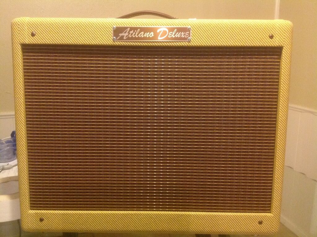
Here is the finished amp. My friend’s last name is Atilano and I had a custom name plate made for him. It turned out pretty awesome.
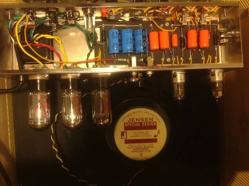
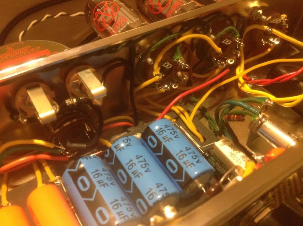
Here is a shot of the back with all the components
GROUNDING
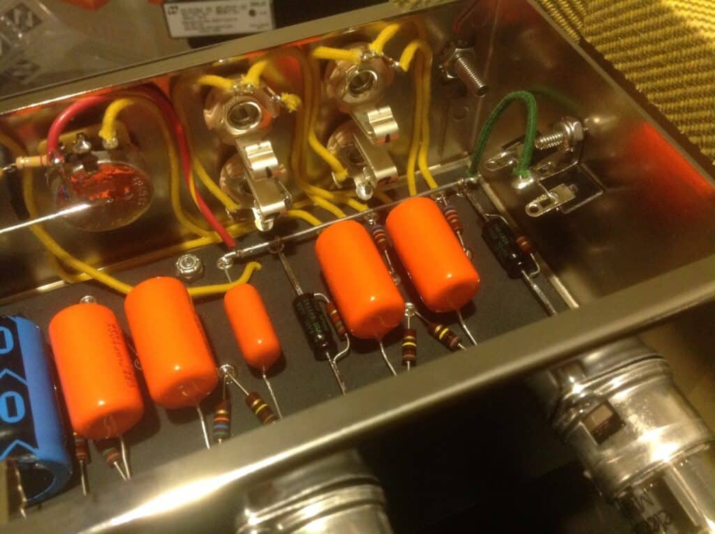
Correct grounding is very important to reduce noise in your circuit. I grounded the preamp section and the power section to two different points on the chassis. For the preamp section I put in a grounding bar with some spare solid core cable. I grounded the power section to one of the screws of the power transformer. Here is a picture of the preamp grounding. From the picture it looks like all the components are connected, but just a few of them are. The green cable is hooking the grounding bar to a mount on the chassis.
6 GREAT MODIFICATIONS:
1. Diodes
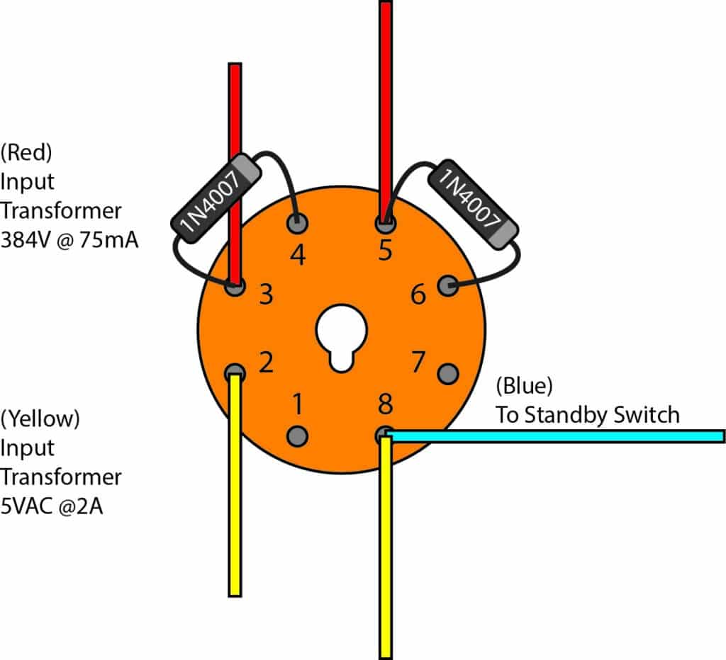
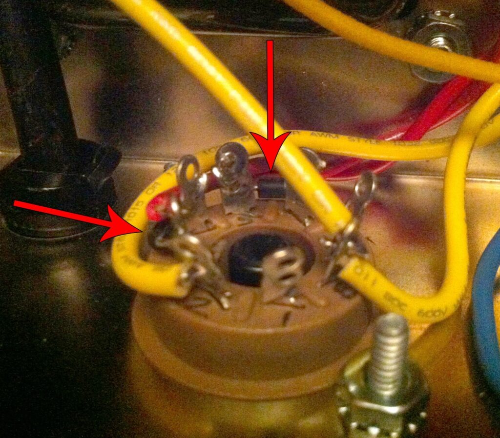
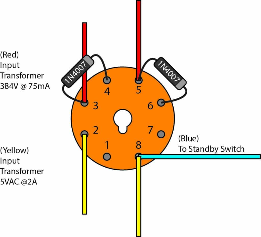
The first upgrade I did to the original design was to put in a couple 1n4007 diodes between the power transformer and the rectifier tube. These diodes will keep AC from your transformer from getting into your amp when your rectifier tube dies. This is an EASY mod that costs less than 50¢ and will help keep from frying other components and lengthen the life of your rectifier tube. The diodes are installed from pin 3 to 4 and from pin 5 to 6.
2. Bleeder resistor
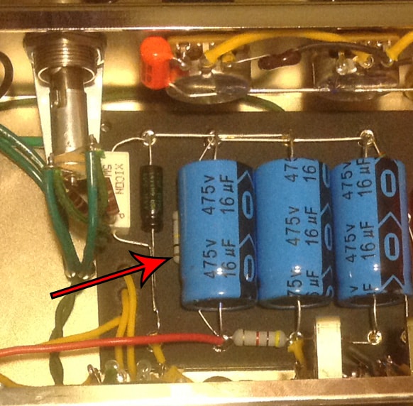
Another very EASY safety feature that only costs about 8¢ is a bleeder resistor. I added a 100K 2W resistor to the power filtering capacitors. The resistor is added to the first filtering cap’s positive side to the ground. This resistor will drain current from the capacitors after the amp is turned off. If you need to do some maintenance on your amp this resistor will keep you from getting a nasty shock.
3. Standby switch
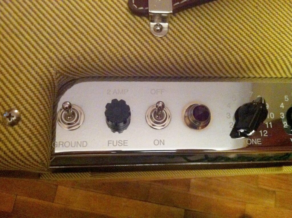
Originally this amplifier did not have a standby switch. It only had a ground lift switch.
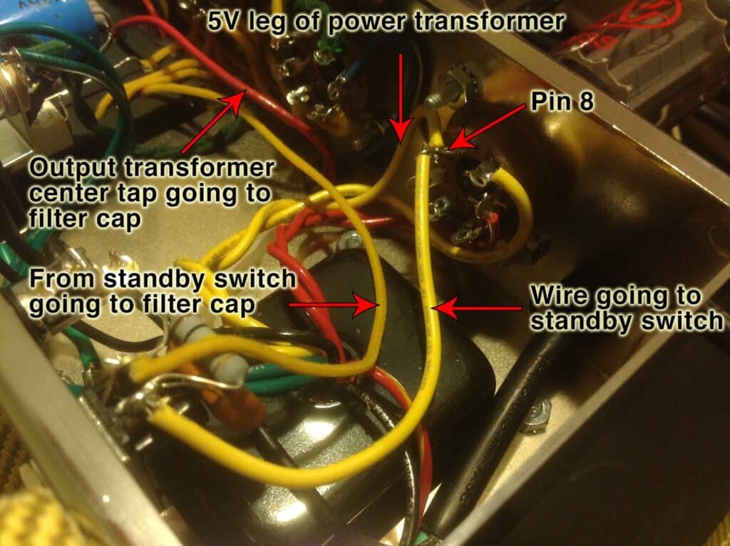
Normally pin 8 of the rectifier tube has 3 wires soldered to it. One of the power transformer’s 5V legs, the center tap of the output transformer, and a wire connecting to positive side of the first filtering capacitor.
Converting the ground lift switch to a standby switch is a fairly simple process. Only 2 wires will be soldered to pin 8 of the rectifier tube. One of the power transformer’s 5V legs and a wire connecting pin 8 to one side of the standby switch. The other side of the standby switch is hooked to the positive side of the first filtering capacitor. Additionally, the center tap of the output transformer is also soldered to positive side of the first filtering capacitor.
4. Pop Protection
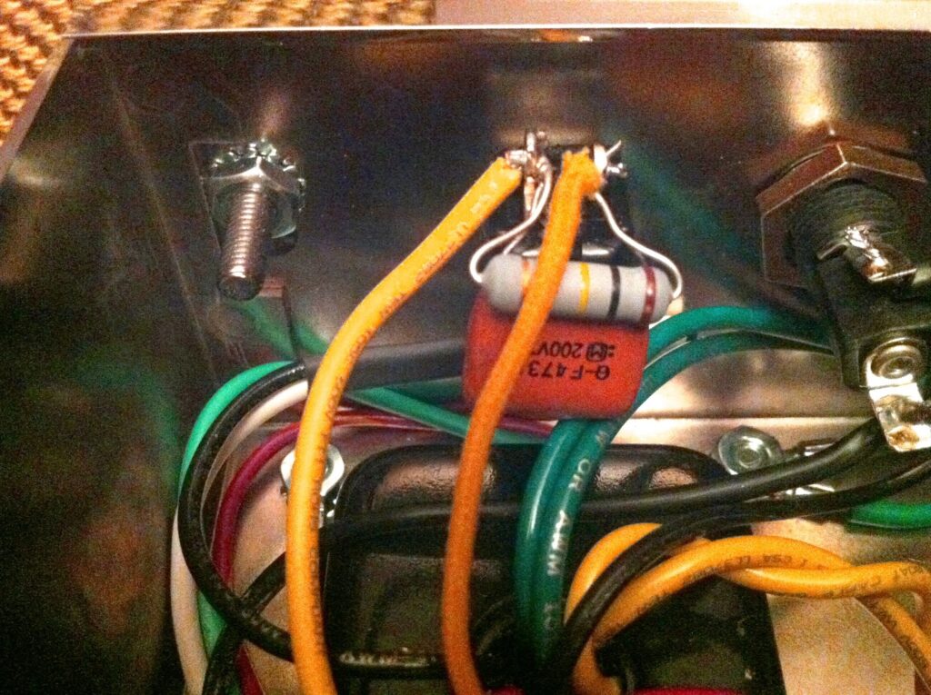
On the new standby switch I also added a capacitor and resistor wired in parallel. Adding this mod will eliminate or significantly reduce the standby switch “pop”. It works by allowing a small amount of current to bypass the standby switch and flow into the filtering capacitors. When toggling the switch those components prevent current from surging. I used a 100K 2W resistor and a .047uF ceramic capacitor.
5. MojoTone Volume/Tone Mod
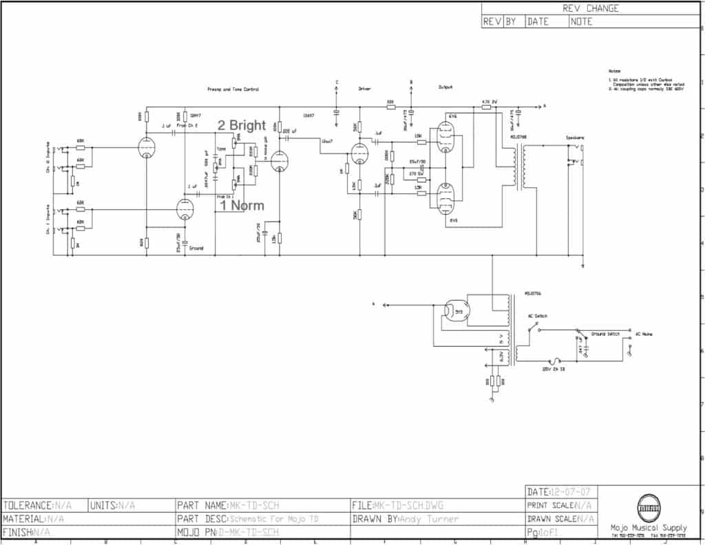
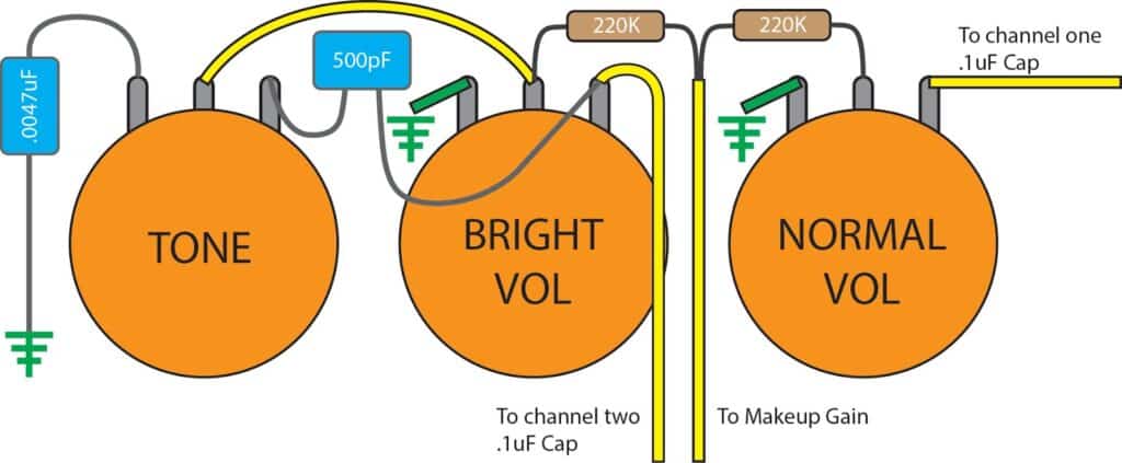
I decided to try the MojoTone Vol/Tone mod. Their schematic says that it will give the amp independent volume control as well as a smoother taper. That sounded good to me! I was having trouble reading the schematic and hooked up one of the volume pots in reverse. Luckily, I worked out the problem before I mounted the pot in the chassis. So that you don’t make my mistake I created a schematic and layout to help do this mod right the first time. Here is a schematic with the Vol/Tone mod inserted in.
Here is an illustration of how to wire the Vole/Tone mod.
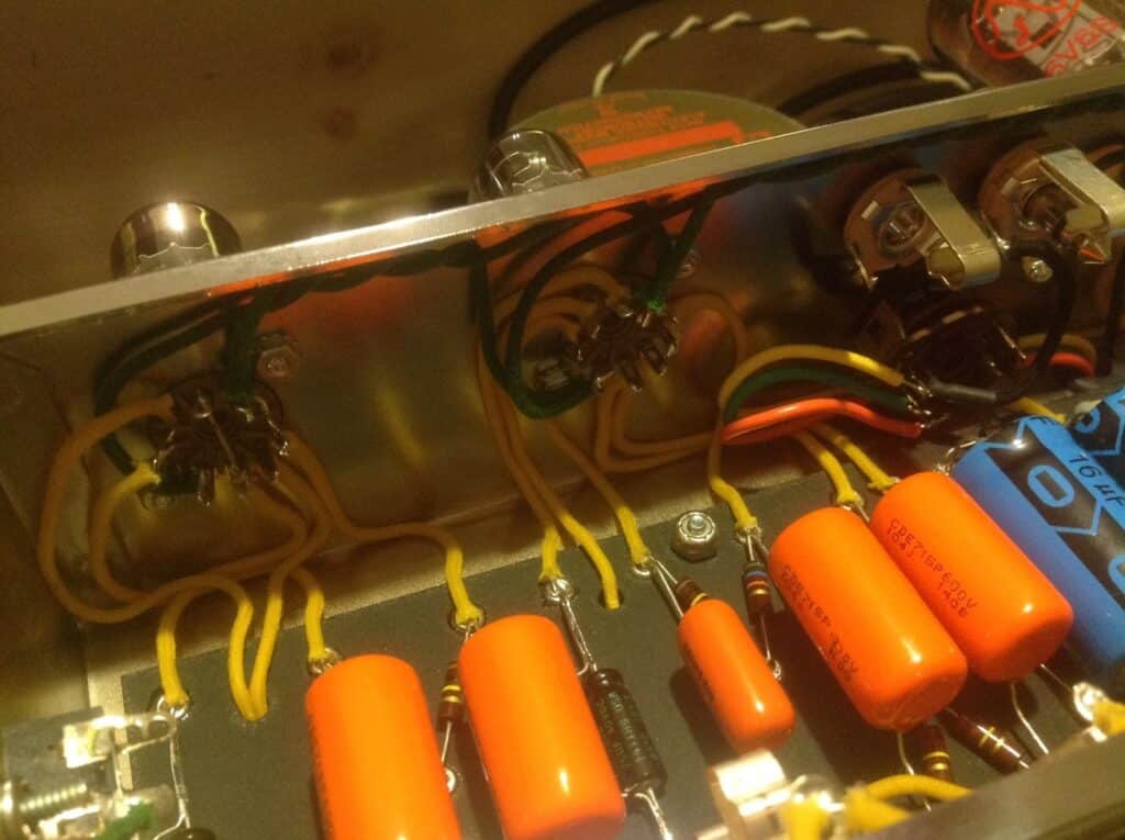
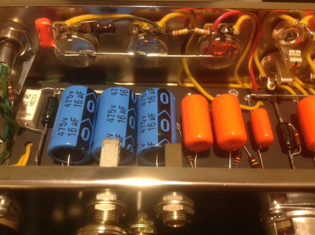
Here is a picture of how I soldered the Vol/Tone mod.
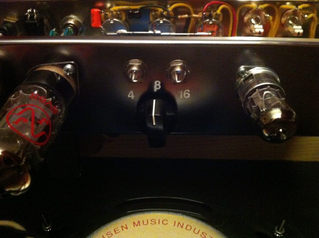
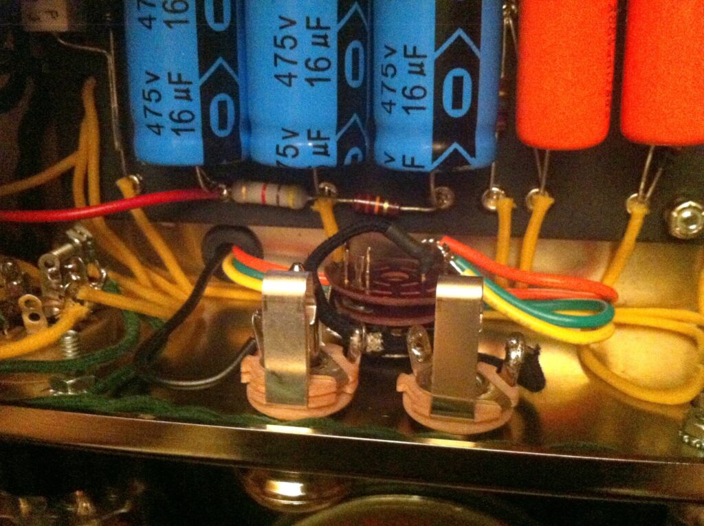
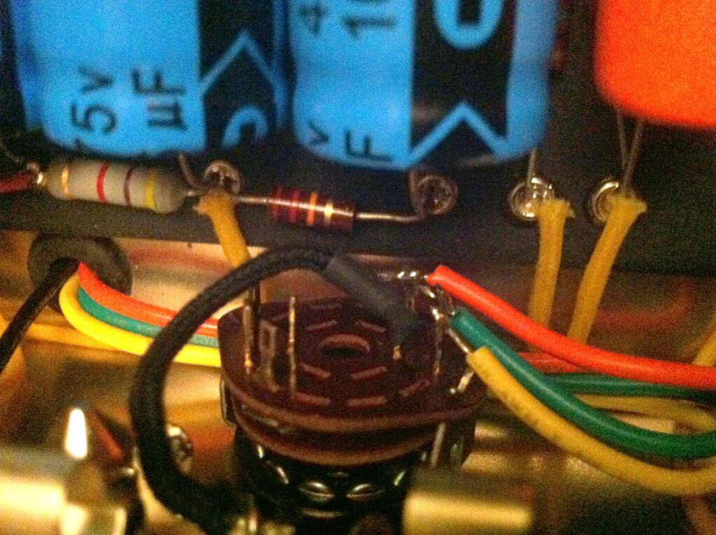
6. Output Transformer Ohm selector SP3T switch
I wanted to make it easy for my friend to change out the speaker if he ever felt like upgrading it. To do this I specified the Mojo 768SP output transformer when checking out online. It has taps that accommodate 4, 8, or 16 ohm speakers. You’ll also need to pick up a SP3T (single pole triple throw) switch for this mod. Tanner’s, the electronics store up the road from me only had a DP3T switch. A DP3T switch will work just fine; I just didn’t use one side of it. The black wire is the start of the transformer’s winding. I soldered that wire to the 1/4″ jack’s ground. Next I soldered a wire (The black one in the picture below) from the 1/4″ jack’s tip to the pole of the DP3T switch. I soldered the 4, 8, and 16 ohm taps to the separate throw legs of the DP3T switch. Luckily, I had some rub on decals from a previous build so I was able to label the switch too. I suggest getting your speaker installed and selecting the correct load with the switch before cranking up the power.
CONCLUSION
This amp build went a little slower than I expected, but in the end it turned out fantastic. Previously, I had only heard new Fender Deluxe amps and was very underwhelmed. The MojoTone 5e3 amp is a different beast. It seems to stay clean much longer before breaking up. The new Deluxe amps break up when the volume is at 2! This 5e3 circuit has a wider range of tone by far.
Have an idea for a video or article?
Drop me a line and let’s learn something cool together!


